Current Position: 24 3.582’N 109 47.467’W (Ensenada de Los Muertos); Course: At anchor; SOG: N/A; BSPD: N/A; TWS: 12.0 kn; TWD: 355 degree; TWA: N/A; Distance to waypoint: N/A;
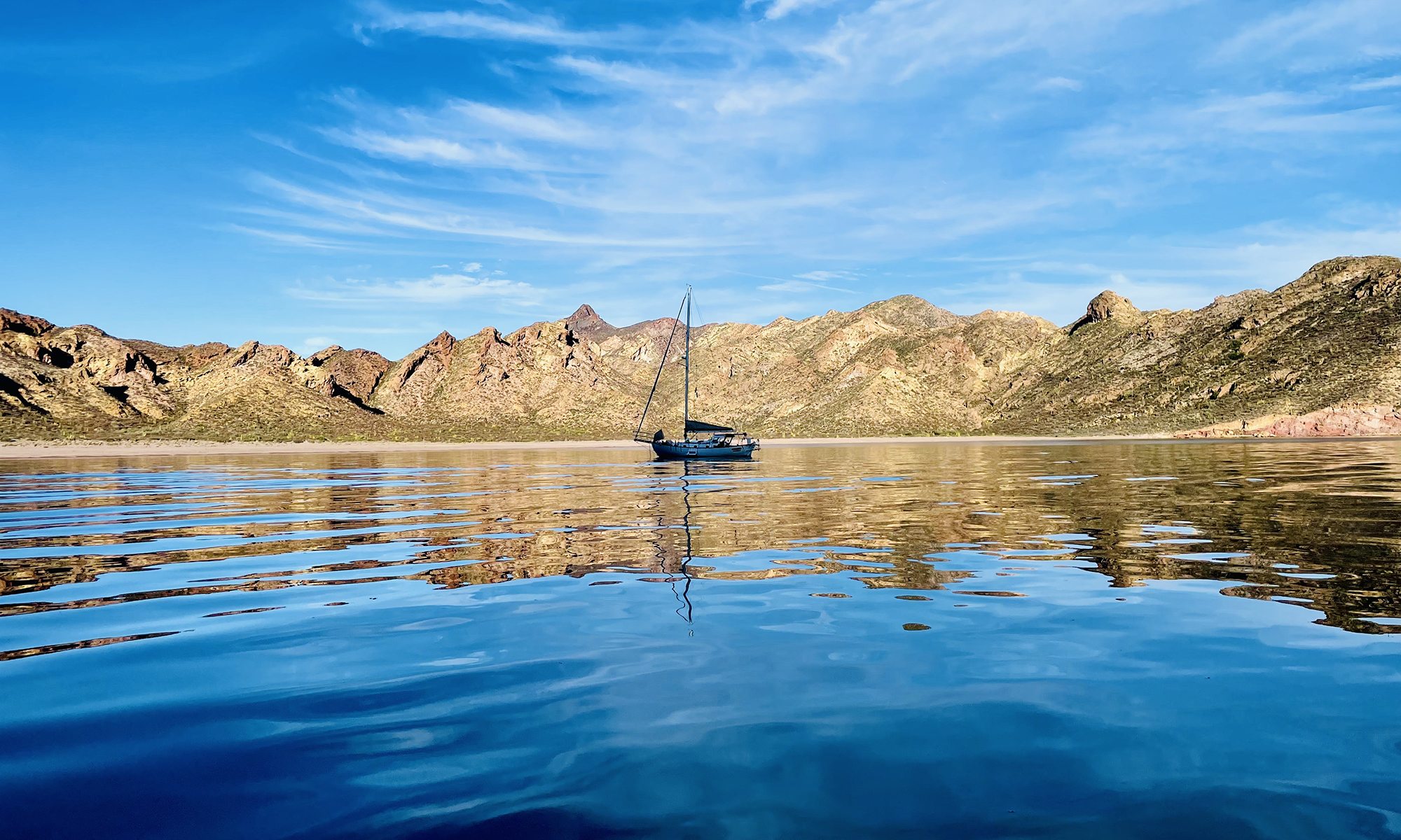
Comments: The bay I am anchored in is teeming with life. There is a huge school of fish around the boat, jellyfish are floating everywhere, there is some sort of battle taking place a 100 yards away, and I just saw a half dozen rays fly. It has been a busy day. Woke up and got my morning exercise putting and eye splice in the line I use as a preventer (to prevent accidental gibes). Replumbed the fuel system to deal with the foaming/air problem in sporty seas (and added the ability to switch between the main and day tank with a couple of valves, reinforced a couple of stanchions that support the dive platform on the port side, and cleaned up after the bird party last night. The winds have been warm and southerly, but as PredictWind predicted, they shifted to the north about 16:00, and the wind picked up. The boat pivoted on the anchor 180 degrees in about 10 minutes.
Sent from my iPhone


