The last time I want sailing I felt a ringing in the tiller that suggested there could be some delimitation. A series of holes were drilled, filled with epoxy, and dowels were driven in. I am going to look into having a new tiller manufactured.

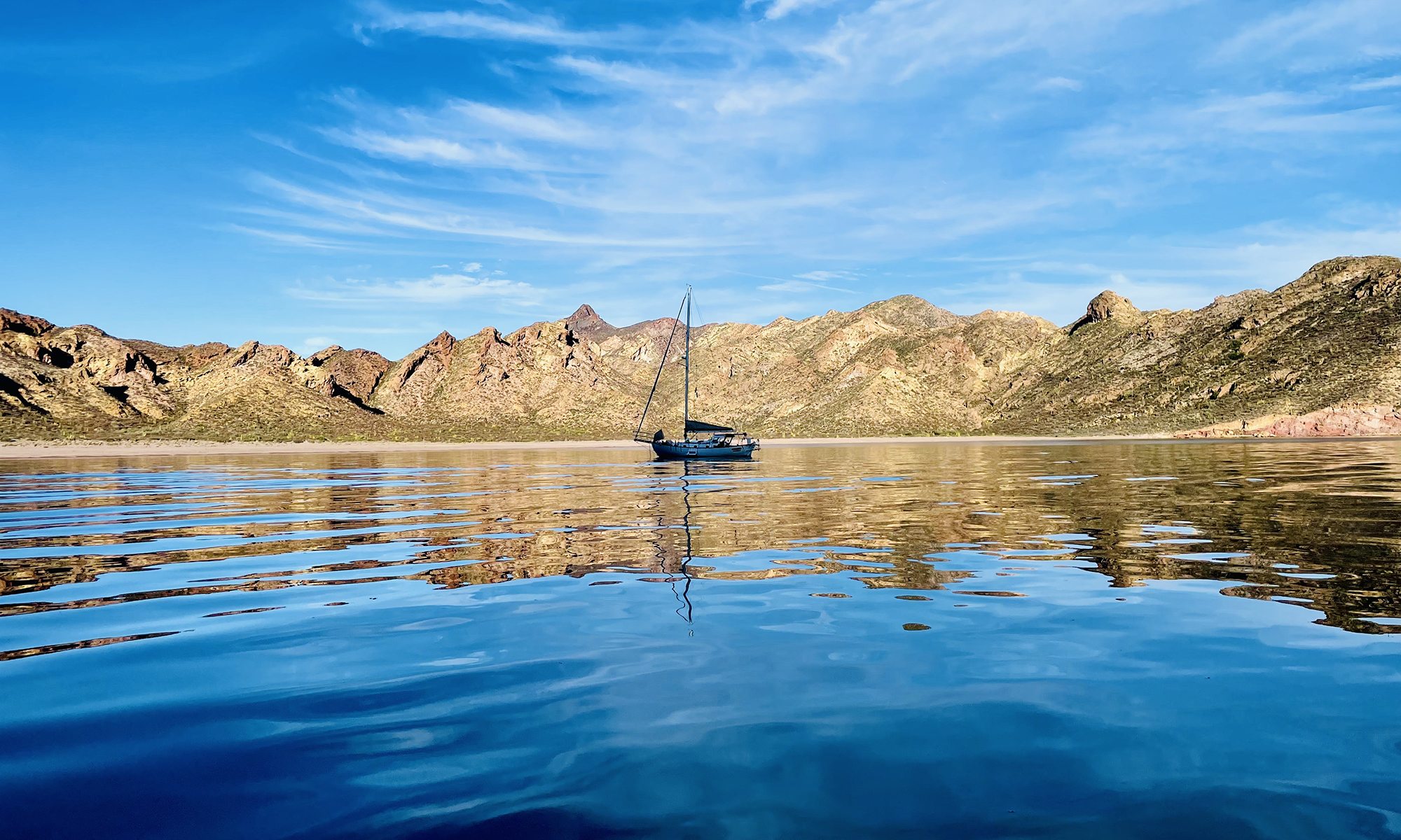
Alajuela 38
The last time I want sailing I felt a ringing in the tiller that suggested there could be some delimitation. A series of holes were drilled, filled with epoxy, and dowels were driven in. I am going to look into having a new tiller manufactured.
A pad eye was installed right outside the companionway so I can clip in when exiting the cabin. The long end of the double leash is just long enough to navigate the cockpit without any chance of going overboard.

For some reason, the boat did not have running backstays. Fortunately, the hardware was in place on the mast. A 1/4″ Dyneema line was attached to the mast and terminated with a thimble. To the Dyneema line was attached a 4:1 fiddle block with 1/2″ double braid with an eye splice. the pulley was attached a 1 1/4″ T-track using a shackle (so the stay can be easily stored at the base of the shrouds).

The shackle was attached to a vintage Merriman Brothers track slide. Unfortunately, the slide on the starboard side was missing. However, I was able to find one on eBay,

After three days crammed into the engine room, the first components of the new Victron system have been installed. Most challenging was the Victron MultiPlus Compact 12/2000/80-50 120V VE.Bus Inverter Charger (on the right) with a Victron VE.Bus Smart Dongle and Victron Energy 200/200 amp Digital Multi Control Panel GX. Because of the size, there were very few places it could be mounted. Eventually, I was able to shoehorn it into the location of the charger that was replaced (a 20 amp Xantrex charger). The new charger was throttled to 50 amps.

The other components of the system were mounted on a board. These components includes (from bottom to top) a Victron Energy SmartShunt 500 amp Battery Monitor, a Victron Energy Smart Battery Protect 12/24-Volt 100 amp, a Victron Energy Orion-Tr Smart 12/12-Volt 30 amp 360-Watt DC-DC Charger, and a Victron SmartSolar MPPT 100/50 Charge Controller. Also on the board are 60 amp Blue Sea Systems breakers that protect, the DC-DC charger and solar controller, the smart dongle and a Blue Sea Systems MEGA 300-AMP fuse and Blue Seas Systems switch that protects the inverter/charger. As of today, only the inverter/charger, shunt, and battery protectors are connected, and once connected via Bluetooth, all the components appear to work as expected.
Whelp … enjoying a glass of Sauvignon Blanc on the bow sprit this evening and noticed the starboard upper shroud (circled in red) is slack.
I have been searching for information on the massive windlass on the boat for some months, but until now have not had any luck. However, I finally found a photograph of a the windlass on the web. it is a Monica Marine Model 1000 windlass. Unfortunately, parts are unavailable.

I have installed Starling RV on the boat. The Mexican version was purchased, which is much cheaper than in the US ($410). Service is also cheaper ($65/month). I am getting 200 Mbs in Marina San Carlos.

I sewed a cover for the butterfly hatch today. An unique aspect is the one-inch PVC filled with sand that weighs down the edges, making it unnecessary to cinch down the cover.


To integrate the chart plotter, radar, and autopilot, an electronic compass needed to be installed. I chose a Precision-9. In addition to reporting direction, the device also reports pitch and roll, and so it should be mounted at the center of gravity in the boat, preferably at the waterline. After exploring possibilities, we decided on mounting the compass on the mast below deck. The problem was the mount was designed for a flat surface. We started by tracing the contour of the mast where we wanted to mount the device.

We then used a table saw to cut the mount out of a block of wood.

Note the contour is rough-cut with the table saw. That surface was filled with epoxy (combined with an epoxy filler), and it was sanded and painted with enamel (on the right, the block on the left is a spacer for the wind instruments).

The adapter was used in combination with the compass mount to install the compass on the mast.

The Alajuela 38 has a new home in Marina San Carlos.
