Aegir-Ran has been without a working engine since its Westerbeke 35C seized up earlier this year. After a two month effort, she has been repowered with a Beta Marine 38. After removing the transmission of the Beta, it was lifted into the cockpit.
Because of the hard dodger, it was necessary to manhandle the engine into the companionway, where I had constructed a gantry crane to lower it into the galley.
The engine was lowered onto a platform I had built in the galley, which was the right height to slide the engine onto the rails.
Despite a model of the engine had been built, it was necessary to modify the brackets for the engine mounts to properly align the transmission with the prop shaft. After completing the electrical and plumbing the engine, we found it fired up instantly.
There are only a few things on Aegir-Ran that require 120 volts : Starlink, laptop charging, the ice maker, and the milk foamer. Running the inverter for these items is problematic: 1) it wastes some energy, perhaps 10-20% (which is lost as heat), 2) It makes an audible noise, and 3) it creates electrical noise that interferes with some of the electronic equipment, like the VHF radio. Of these applications, Starlink is used most often, so I decided to convert it to 12 volts. My first effort was home-built, but I found the results to be unreliable. I subsequently read that Starlink is particularly sensitive to electronic noise (because the cable between the antenna and the modem is used for both power and for data). I turned to a commercial product, the XTAR-LINK.
The $200 plug-and-play XTAR-LINK comprises of: 1) a (cheap) 12 volt router, 2) a box that includes power injector (POI), a transformer that bumps 12 volts to the 48 volts that Starlink uses, and cross-over wiring that converts the proprietary wiring scheme of Starlink to the T568. Ethernet standard, and 3) a box accepts the proprietary Gen 2 Starlink router plug. Once assembled and the router was programmed, the system fired up immediately and has run for a month without incident. I have not measured the energy savings, but XTAR-LINK claims “up to 30%”, which is the result of not having to run the inverter and because the router is more energy-efficient. I have found the router that was provided operates at a longer distance than the Starlink one does, and it has the advantage of having Ethernet and USB ports (which for example can be used for a data drive).
Since I have changed the fuel storage and I am replacing the Westerbeke 35C with a Beta 38, I need to re-estimate the range under power. I previously estimate the range to be 625 NM.
And, considering the tankage of 60 gal for the main tank + 15 gal in the day tank + 30 gal on the deck = 105 gal total, assuming 2200 RPM (fuel consumption is about 2.0 l/h = 0.53 gal/h), and assuming Aegir-Ran would achieve 5 NM/h at 2200 RPM, I calculate a range of:
1 h/0.53 gal x 105 gal = 198 h; 198 h x 5 NM/h = 990 NM
Once the boat splashes, I will begin keeping an accurate fuel log.
Now that I have fuel level sensors and a fuel monitoring system on the NEMA 2000 network, I will start keeping closer track of actual fuel usage.
I looked around for a harness for my outboard motor. After reading several negative reviews and speaking with a friend who was disappointed with his purchase, I decided to make my own. The main problem with the existing harnesses is they are “universal”, and so do not fit a particular motor very well. I sewed a custom harness for my Yamaha F6 in about 30 minutes. It probably cost $2 in material, saving me over $50.
I have a TIP (Temporary Import Permit) for Aegir-Ran which in principle lets me import replacement parts duty-free. However, every time I cross the border and show the paperwork, the import officials do not seem to know anything about the permit. Naturally, I was concerned about importing a new/expensive engine, so I collected advice from many fellow sailors regarding the process. Unfortunately, I obtained conflicting advice, especially with respect to whether I would need to remove the old engine from Mexico. S/V Pono imported a engine two years ago, so I followed their recommendation.
Since I traded my Westerbeke 35C for labor, the diesel mechanic gave me a dead Yanmar engine to take across the border. I figured this would work because my TIP does not actually list the make of the engine. It does list the serial number, but I took a chance that the officials would not look too closely. As it turned out, that was the case.
The trip to the US was quite an adventure. I borrowed a 1995 Dodge Dakota pickup. About 50 miles from the border, the idle pulley bearings failed, throwing the serpentine belt, which slammed into one of the water hoses, cracking the radiator. I got a ride to the nearest Autozone, got a new pulley, and installed it on the road. However, I did not have the tools to replace the radiator. I limped to the border a few miles at a time, stopping to refill the radiator. On the way, I stopped at the Banjercito, which is located just south of Nogalas (Carretera Nogalas-Hermosillo KM 21, 84107 Nogalas). Parking to the north of the group of building, I walked through the building to the back, where the Banjercito was located. After showing Aegir-Ran’s TIP, I requested two forms that are called “Registro de importacion temporal.” One form is for export of the old engine and the other for import of the new engine (shown below).
The only difference between the two forms is the export form lists the serial number for the old engine and “Sestitucion” is checked whereas the other form lists the new engine and “Integracion” is checked (circled on the form. The official at the Banjercito did not want to see the old engine.
I limped across the border. Fortunately, there wasn’t a line at 6:00 PM on a Friday going north (although there was a huge line going south). The US Border Agent did not believe my story about the old engine in the truck bed, so I had to have the truck X-rayed. Fortunately, that did not take too long. Once I crossed the border, I contacted a radiator shop to make an appointment in the morning and I got a room a mile away from the shop at a Motel 6 in Nogalas. In the morning, I took the truck to the shop. They worked all day on the truck and eventually had to order a new radiator from Tucson. Finishing the work about 6:00 PM, I drove to Tucson.
The next morning, I dropped the old engine off at a recycling center (I got $25 for the 450 lbs of steel) and I went to the freight company where they loaded the new engine with a forklift.
The next day I drove to San Carloes. The customs agent wanted to see both forms I had obtained from the Banjercito, and then passed me through.
I had no further problems with the truck. When I arrived, the engine was removed from the bed of the truck and placed next to Aegir-Ran. I have a few weeks of work to do in the engine room before I will be ready to install the engine.
I have been putting off buying foul weather gear, in part because I have not needed it in the Sea of Cortez, but mostly because it is so darn expensive. I have been saving my pennies for the past several months, and am now in a place to pull the trigger on several purchases. To make my funds stretch, I have been keeping my eye out for good deals on eBay.
The first purchase was a Gill OS1 jacket (top left). This is a jacket for extreme conditions that retails for $650. I found a “new” one on eBay for $200 that had been the (unworn) backup jacket of the seller. I couldn’t find used OS2 bibs, so I bought a new pair on Amazon for $210 (they retail for $250). From the same seller as the OS1 jacket, I got the yellow bibs for $70. I also purchased the “coastal” (looks like an OS3) jacket on the right for $60. So for less than $550, I got a complete medium-weight and heavy-weight set. The total retail for the four garments new would be about $1,500. Three of the four garments are essentially (or actually) new.
I have been procrastinating purchasing satellite communication equipment because the technology is evolving rapidly. The main use I will have for the equipment is obtaining up-to-date weather forecasts. I have been using PredictWind for the past year and I am convinced this is the forecasting tool I will use. While in principle, I can download PredictWind via Starlink, I do not consider that platform reliable. It’s hard to say when Musk will burn it to the ground and the Starlink offshore data rates have gone up markedly in recent months. Furthermore, the system runs on AC, so if the inverter fails, I will not have access to Starlink. Perhaps most importantly, it is not designed for saltwater/sailing environment. The antenna is subject to damage and the electronics look fragile. Finally, it uses a large amount of power. I do not have the resources to access Starlink when it is cloudy/storming, which is exactly when you most need weather forecasts.
I just purchased an Iridium Go Exec. While the technology is dated, it is reliable. Further, the partnership with PredictWind allows seamless integration. The Iridium Go Exec offers several advantages of Starlink, including it’s stand-alone, it uses much lower power (5% of StarLink), it has battery backup, it is compact, it is rugged, and the data plans are much less expensive. While it retails for $1,600, I found a new one on eBay for the $750. I also bought the DataHub ($300), which allows me to GPS-track the boat, log data, and it allows me to extend the AIS data I receive to 300 NM.
It is now obvious why the engine failed. The flywheel damper plate and adisintegrated. Pieces of the spring/rollers were cut through and jammed against the housing and another loose piece next to the damper plate. Note one piece of spring embedded in the transmission housing.
In the photo above you can also see several of the swings have stopped rotating and have been ground flat. At the 3:00 position you can see a piece of spring missing and at every position you can see groves cut into the spring, ready to release more pieces. The plate itself had been worn, allowing the springs to move back and forth and not simply spin. The photo below shows the flywheel grooved by the piece of spring jammed in the housing, which is what caused the engine to seize.
The Westerbeke 35C in Aegir-Ran seized. Something catastrophic failed inside the engine. The temperature did not rise, the oil pressure was good, and it was not hydrolocked. Since I was 80% certain I was going to repower the boat this summer, the failure of the engine confirmed my suspicion that the engine was on its last legs. I always suspected the engine after I learned the genset in the boat, which was also powered by a Westerbeke 35C had been killed by the previous owner after less than a hundred hours of use. Today, we pulled the old engine out of the boat.
The procedure was non-trivial. We started by disconnecting everything, building a platform for the engine so it could sit in the galley, and with the assistance of a come-along pulling it along a ramp to the platform.
At this point we were able to lift the engine to 2x4s that were placed across the cabinets.
It was out intention to bring the crane in to lift the engine out, but the hard dodger and the solar system didn’t give us enough vertical room, so we used wooden blocks to place the come-along high enough to get the engine out of the gangway. The engine and transmission weigh about 400 pounds, so the operation was precarious.
At this point we were able to manhandle the engine into the cockpit.
Finally, we were able to use the crane to lift the engine out of the cockpit.
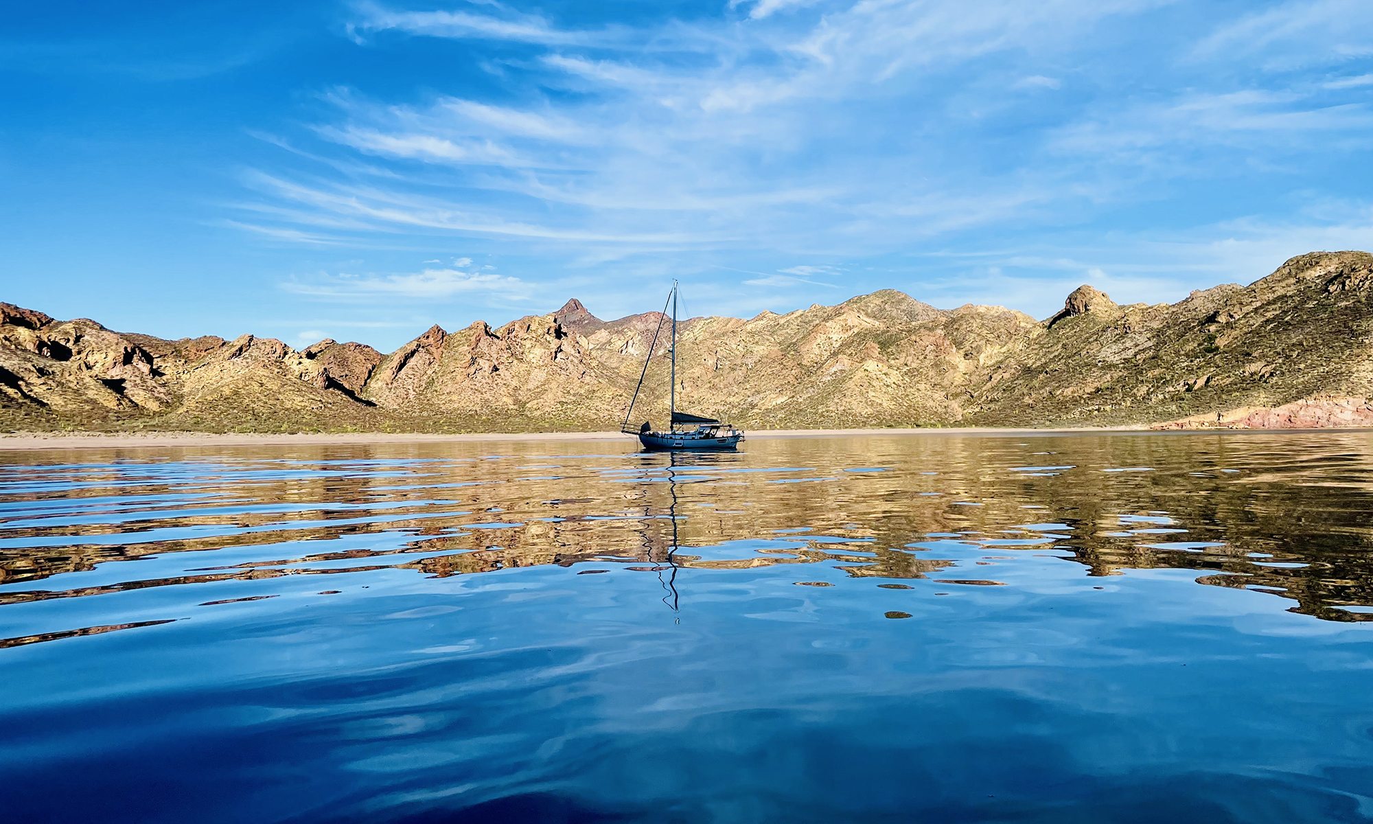
I had been sailing for about a month, crossed from San Carlos to Santa Rosalia, and made my way slowly south down most of the length of Baja, about 400 miles. On March 26th, I was anchoring at Muertos in southern Baja (marked with the red X) and the engine stopped suddenly … on a dime. I immediately checked the temperature and oil pressure, and they were fine. I pulled the injectors and tried to turn over the engine with a wrench, and it would not budge. The engine was clearly not hydrolocked. There had been a catastrophic internal failure. The engine was seized. Considering my predicament, I decided it did not make sense to sail to La Paz to try to get the engine repaired. It appeared there had been an internal failure.
Without an engine, I had to consider a route back to my home port that did not require maneuvering in tight places. As a first step, on March 29 at 4:00 AM, I sailed for Isla Espiritu Sato. Not wanting to negotiate the Cerralvo Channel, I sailed east of Isla Cerralvo. About four-fifths around the island, about 16 miles from the anchorage (Bonanza), the island blocked the prevailing westerly winds and I sat becalmed for about four hours, The north current eventually floated the boat past the island. At the point there wind changed to the SSE and stabilized at 15 knots. The sea conditions were poor with 5′ waves from the east. I anchored at Bonanza at 9:30 PM. I note that my trip from Bonanza to Muertos a few days earlier had taken one-third the time.
The next morning, March 30, sea conditions were not ideal, but there were 15 knot winds from the south, so I left for Isla San Francisco at 8:30 AM, moving briskly at 6 kn with just the jib. While I tries to stay well offshore of Isla Espiritu Santo, I nonetheless got Becalmed about halfway across the island. Around 4:00 PM the wind build quickly to 22 knots, still from the south. I double reefed the main and shortened the jib, but still made the remaining 15 miles before dusk. I reached the eastern anchorage of Isla San Francisco just as it was getting dark. There were five sailboats and a powerboat anchored there. I radioed ahead for advice and was told there was room for me. I explained I would be coming in under sail. Over the next ninety minutes, I tried three times from three different angles to reach the anchorage, but the wind was howling through the notch that connects the southern and eastern anchorages that drove me off each time. Eventually, I radioed that I was abandoning my attempt to anchor and was heading offshore.
After fighting the ever changing wind and sea condition around the islands, I decided to sail directly to San Carlos. I plotted a path well offshore and sailed through the night in a close haul and an average of 22 knots of wind, at times surfing at 8.5 knots SOG. I sailed 60 miles between 9:00 PM and 5 AM (averaging 7.5 knots). I thought about anchoring at Bahia Salinas on Isla Carmen about midday, but upon looking at the weather forecast, I realized this would be the only chance I would have for crossing this week, as later in the week 5-6′ seas were expected. Thus, on March 31, Easter, I decided to continue the 135 miles to San Carlos. There was, however, a problem. I had been sailing about 24 hour since my last anchorage at Bonanza. Sailing overnight, I had run the radar and AIS to geofence the boat and used the TillerPilot, depleting the batteries to 65%. At 50%, the batteries are cut off to protect their health. My pattern had bent rely on the instrumentation and autopilot at night, dozing thirty minute intervals, so I needed power for the next night.Unfortunately, there was very little sun. In fact, the weather was very squally. To save power, I shut down all power consumption, including the instrumentation, radio, autopilot, and even the fridge. I broke out the compass and engaged the wind vane.
I dodged squalls most of the day, sailing 4-6 knots in mostly light winds. That evening, the wind picked up to about 15 knots from the NW and I made good time overnight using the instrumentation and the wind vane. Early afternoon the next day, April Fools day, the wind died down. At 2:30 PM, about 24 miles from San Carlos, I became becalmed. About 6:30 PM, right at dusk, I spotted a squall to the NW. About 9:00 PM, I reached the squall and rode it in to San Carlos. The last mile or two, dolphins swam next to the boat. I anchored at La Posada about 1:00 AM on April 2nd. I had been sailing about 65 hours non-stop.
The next morning was sunny and there was a light breeze of about 8 knots. I sailed around the corner and into the mouth of the Bahia San Carlos. Unfortunately, the wind was blocked by the shore at the point, and I eventually called a friend on S/V Infinity to help tow me in with their dingy. They also towed me in the next morning when Aegir-Ran was hauled out,